
To size an industrial gearbox, begin with the driven machine’s requirements and then check a proposed gearbox against them. Motor power is one input to that process, not a complete specification. A useful selection brief records speed, torque, duty, mounting, external loads and operating conditions together.
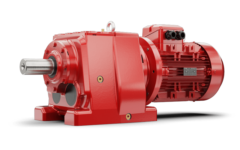
1. Define the output duty
Record the required speed at the machine shaft in revolutions per minute and the torque needed there in newton metres. Identify whether the values are measured, calculated or estimated. If a belt, chain or another transmission stage sits between the gearbox and the machine, show it on the layout and state where each speed or torque value applies.
For steady rotational power at the same shaft, T = 9550 × P ÷ n, approximately, where T is torque in Nm, P is mechanical power in kW and n is speed in rpm. This follows from power = torque × angular speed. Do not put electrical input power into the expression and call the result machine output torque without accounting for the losses in between.
As an illustrative arithmetic check, 4 kW delivered at a shaft rotating at 50 rpm corresponds to approximately 764 Nm. That is an operating-point calculation, not a selected motor or gearbox. It says nothing about starting torque, a jam, thermal capacity or permissible shaft loads. The conveyor torque guide covers the separate task of establishing load for a conveyor application.
2. Describe how the machine actually runs
List hours per day, starts per hour, acceleration time, loaded starts, reversals and the duration of peak loads. Separate normal production from cleaning, setting, inching and fault conditions. If a measurement includes a peak, record its duration and how it was captured; an unexplained maximum number is difficult to use reliably.
Apply the service-factor method for the relevant manufacturer and range. I-MAK’s selection information considers the characteristics of the driven machine. Do not carry a factor from another range or multiply several unrelated margins together without understanding the method.
3. Check the complete installation
The proposed size and ratio still need checks for heat, shaft loading and mounting. Identify radial and axial loads, their direction and where they act. Confirm the intended mounting position, motor connection and available space. With variable-speed operation, provide the required speed range and load at different speeds; the existing VFD guide explains why the motor and gearbox need to be assessed together.
| Information to supply | Record and qualify |
|---|---|
| Machine and process | What it drives; normal operation; unusual or fault conditions. |
| Output speed and torque | rpm and Nm; measurement point; measured, calculated or estimated. |
| Load pattern | Continuous duty, starts, reversals, peaks and their duration. |
| Motor and controls | Motor plate, supply details, starting method and speed range. |
| Mechanical interface | Drawing, mounting position, shaft connection and external loads. |
| Environment | Ambient range, dust, moisture, washdown or other application requirements. |
| Open questions | Unknown values, who will establish them and the evidence required. |
4. Confirm the proposed selection before ordering
Ask for the exact type designation, ratio, motor arrangement and drawing. Check that the rating assessment uses the same duty and mounting assumptions as your enquiry. Record any conditions attached to cooling, lubrication or allowable loads so they are not lost when purchasing or installation is handed to another person.
A larger motor is not automatically a remedy for an underspecified duty: it can change the torque available to the mechanism. Equally, a physically larger gearbox does not remove the need to verify the motor, controls and machine interfaces. Recheck the assessment when the operating requirement changes.
Use the product range to identify possible layouts, then send Advanced Drives your selection worksheet and drawings. Where an input is uncertain, mark it as uncertain. Resolving that question is more useful than selecting a housing around an unsupported assumption.
Technical references
For the exact unit, use its confirmed drawing, applicable catalogue and operating instructions. The following references support the principles discussed here: