
Matching replacement gearbox dimensions means checking the interfaces with the machine, not just finding a housing that looks similar. The shaft, mounting, motor connection and removal space all matter. Use a dimensioned drawing to compare the existing assembly with the proposed replacement before ordering.
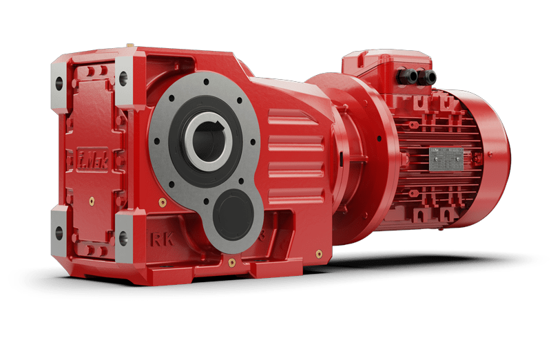
The replacement gearbox service page explains how to start an enquiry. This guide provides the more detailed dimensional record that helps turn a nameplate match into a checked installation proposal. Physical fit and suitability for the operating duty are separate questions.
Start from a consistent set of reference points
Use the existing manufacturer’s drawing where it is available. Identify the mounting face, shaft shoulder and shaft centreline on your sketch before writing down measurements. A shaft projection measured from a housing face may not be the same as one measured from a flange face; name the reference surface rather than sending an unlabelled length.
Photograph the complete arrangement from several directions and include the motor, couplings, guards and adjacent structure. Only inspect or measure machinery under the site’s safe isolation and access procedures. Do not remove guards or reach into an operating drive to obtain a dimension.
| Interface | What to record |
|---|---|
| Solid output shaft | Diameter, usable projection, shoulder position, keyway details and retaining arrangement. |
| Hollow output | Bore or spline specification, engagement length, connection type and access from each side. |
| Foot mounting | Hole centres, hole or slot sizes, mounting-plane dimensions and shaft centre height. |
| Flange mounting | Pilot/register diameter, bolt circle, number and size of holes, and flange-face position. |
| Motor interface | Motor frame and mounting designation, shaft and flange drawing, adapter or coupling details. |
| Torque reaction | Torque-arm location, attachment arrangement and available movement or clearance. |
| Service envelope | Space to withdraw the gearbox or motor and reach plugs, fasteners and inspection points. |
Show orientation as well as dimensions
Mark the gearbox’s installed position, which side carries the input and output, and the viewpoint used for any rotation arrow. Note equipment above, below or behind it that restricts access. The mounting-position guide explains why orientation also affects matters such as lubrication and plug positions.
For a shaft-mounted arrangement, record how the housing’s reaction is restrained and how the unit is supported during removal. If you are considering IRO or IRNX, compare the exact selected configuration and its installation requirements. A hollow shaft of the same nominal diameter does not prove that the full connection is equivalent.
Use a marked comparison, not a verbal “looks right”
Put the existing and proposed drawings beside one another. Mark each critical dimension as matched, different or unconfirmed. Where a difference appears acceptable, record the proposed alteration and who will check it. This avoids a nominal match being treated as approval to change a mounting plate, shaft connection or guard.
Keep the dimensional record linked to the gearbox and motor nameplates. Supply the ratio, output speed, operating duty and any available load information separately. An assembly can fit in the available space while still needing a different speed, torque capacity or thermal assessment.
Send a complete replacement enquiry
- Clear photographs of both nameplates, plus the complete installation.
- The existing drawing or a labelled measurement sheet with units.
- Shaft, mounting and connection details, including any non-standard parts.
- The machine duty and the required output speed.
- A list of dimensions or conditions that remain unconfirmed.
Advanced Drives can use these details to investigate an I-MAK replacement and provide the proposed drawing for comparison. Send the replacement details before committing to changes on the machine. Compatibility should be established for the specific assembly; it should not be assumed from a similar product name or housing shape.
Technical references
For the exact unit, use its confirmed drawing, applicable catalogue and operating instructions. The following references support the principles discussed here: