

A conveyor torque calculation starts with the force needed to move the conveyor and the radius of its drive pulley. For a belt conveyor, running torque at the pulley is effective belt pull multiplied by pulley radius. Starting, acceleration and stopping must then be checked separately before selecting the motor and gearbox.
This guide covers a belt conveyor driven through a pulley. Screw conveyors, vibrating screens and other mechanisms need their own load calculations; their resistance cannot be found simply by applying a belt-conveyor friction estimate.
1. Establish the conveyor load and effective belt pull
Record the conveyor length, lift or incline, belt speed, pulley diameter, maximum material loading and operating pattern. Obtain the effective belt pull from the conveyor designer’s calculation or suitable measured data. It is the difference between the tight-side and slack-side belt tensions at the drive pulley, not the weight of material on the belt.
The calculation needs to include the relevant belt and idler resistance, material lift, skirts, cleaners and transfer conditions. On an incline, the material’s gravitational resistance is one contribution to the total. A single friction coefficient applied to the material mass is not a complete calculation for every conveyor.
2. Calculate pulley torque, speed and power
- Running torque: T = F × r, where T is torque in Nm, F is effective belt pull in N and r is pulley radius in m.
- Pulley speed: n = 60 × v ÷ (π × D), where n is rpm, v is belt speed in m/s and D is pulley diameter in m.
- Mechanical power at the pulley: P = F × v ÷ 1,000, in kW. Equivalently, P = T × n ÷ 9,550.
Keep the measurement point clear. These are pulley-shaft requirements. Allow for losses between the motor and pulley when calculating motor-shaft power, and include any additional belt or chain ratio when selecting the gearbox ratio.
Worked example with stated assumptions
This is an illustrative calculation, not a completed installation or a gearbox recommendation. Assume an effective belt pull of 1,500 N, a 200 mm diameter drive pulley and a belt speed of 0.5 m/s.
- Pulley radius is 0.1 m, so running torque is 1,500 × 0.1 = 150 Nm.
- Pulley speed is 60 × 0.5 ÷ (π × 0.2) = about 47.7 rpm.
- Power at the pulley is 1,500 × 0.5 ÷ 1,000 = 0.75 kW.
- With an assumed overall mechanical efficiency of 90%, required motor-shaft power at this operating point is 0.75 ÷ 0.90 = about 0.83 kW.
- A motor running at 1,400 rpm would need an overall reduction of approximately 29.3:1.
The assumed efficiency must be replaced with data for the proposed arrangement. These running figures do not establish the motor rating or gearbox size: loaded starts, acceleration, service factor, thermal capacity and shaft loads remain to be checked.
3. Check starting duty and gearbox service factor
A loaded restart can require more torque than steady running. Establish the breakaway load, acceleration time and inertia, then check the motor and drive’s available torque against the gearbox’s permitted peak load. A service factor is not a substitute for this check or for overload protection during a jam.
Use the selected manufacturer’s service-factor method for the load class, hours per day and starts per hour. Avoid treating 1.5 or 2.0 as a universal conveyor factor, or applying overlapping margins without understanding what they cover. Our quarry conveyor guide discusses the additional selection questions for bulk handling.
4. Choose the arrangement and check its limits
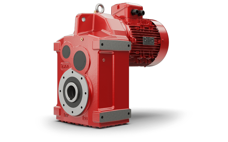
The I-MAK YP parallel shaft range is one option where its layout and ratings suit the conveyor. Compare it with the other ranges on our conveyor drives page.
Confirm thermal capacity, mounting position, lubrication, output-shaft loads and the required stopping or reverse-motion control. For variable-speed operation, check the complete speed and torque range, including motor cooling at low speed. See our VFD and geared motor guide.
What to send for a conveyor drive enquiry
Send the effective belt pull or conveyor design calculation, pulley diameter, required belt speed, maximum load, incline, running hours and starts per hour. For a replacement, include the gearbox and motor nameplates, mounting photographs and drawings. Contact Advanced Drives to discuss an I-MAK selection against that duty.
Further technical reading: Oriental Motor technical reference, including belt-conveyor motor sizing. Use the ratings and selection method for the actual equipment proposed.