
Hollow-shaft gearbox connections join the gearbox output to the driven shaft. Two common approaches are a keyed connection and a frictional connection made using a shrink disc. Choosing between them requires more information than the nominal shaft diameter.
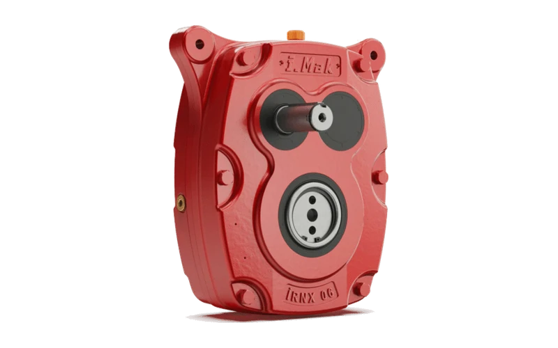
A shaft-mounted arrangement describes how the gearbox sits on the machine. The connection describes how torque passes between its hollow output and the driven shaft. The housing also needs the correct means of reacting torque. These are related decisions, but one does not replace the others.
How the two connections work
In a conventional keyed connection, a key engages matching keyways in the shaft and hub to transmit torque. The drawing must define the bore and shaft fit, key details, engagement and axial retention. Do not assume that the key alone provides every locating or retaining function required by the assembly.
A shrink disc applies pressure externally to the hub or hollow shaft. The resulting clamping force creates a frictional connection at the shaft-to-hub interface. RINGFEDER’s technical explanation distinguishes this external arrangement from an internal locking assembly. The connection must be selected and assembled to the instructions for the actual components; it is not made by choosing a bolt torque from a generic table.
| Question | Keyed hollow shaft | Shrink-disc arrangement |
|---|---|---|
| Which drawing details matter? | Bore and shaft fit, key/keyway dimensions, engagement and retention. | Shaft and hollow-shaft geometry, specified fits, surface requirements and clamping unit. |
| What access is needed? | Access to the retaining arrangement and sufficient withdrawal space. | Access to the locking screws, guards and the specified release/removal arrangement. |
| What must be checked? | Connection capacity and the complete mounting arrangement for the duty. | Permitted torque and any combined loads for the exact connection. |
| What should not be assumed? | That the same bore diameter means the key and fit are compatible. | That every hollow shaft can accept a shrink disc or that one procedure fits every design. |
Treat the shaft as part of the specification
Provide the driven-shaft drawing, including material and any sleeve, step, groove or existing damage that may affect the proposed connection. State whether it is a new shaft or an existing one that must be retained. If the dimensions are unknown, identify them as outstanding rather than translating a rough field measurement into a manufacturing tolerance.
Include the duty: operating torque, peaks, reversals and start frequency. The gearbox, shaft connection and reaction arrangement need to be assessed together. A catalogue gearbox torque rating does not, by itself, establish the capacity of a separately selected connection.
Plan for removal before installation
Show how far the gearbox can move along the shaft and whether nearby bearings, guards or steelwork limit access. Ask which removal provisions belong to the selected configuration. Keeping a clear removal path is a useful design question even when the drive will only be disturbed during a planned overhaul.
Use the manufacturer’s instructions for surface preparation, lubrication where specified, tightening and release. Requirements can differ between the locking assembly, its screws and the mating shaft surfaces. General advice to grease everything, or to assemble everything dry, can therefore be misleading.
Information to include in an enquiry
- Gearbox type and the exact output-connection option being considered.
- Driven-shaft drawing and the dimensions that must remain unchanged.
- Torque, speed, external loads and the operating cycle.
- A sketch of the torque-reaction arrangement and available access.
- Environmental conditions and any corrosion or cleaning requirements.
The shaft-mounted gearbox guide introduces the wider selection questions for IRO and IRNX. For a new enquiry, explore IRNX, IRO or YP as appropriate, then ask Advanced Drives to confirm the available connection for the chosen model. These links identify relevant ranges; they do not imply that both connection types are available on every size.
Technical references
For the exact unit, use its confirmed drawing, applicable catalogue and operating instructions. The following references support the principles discussed here: